Comfort 300LR

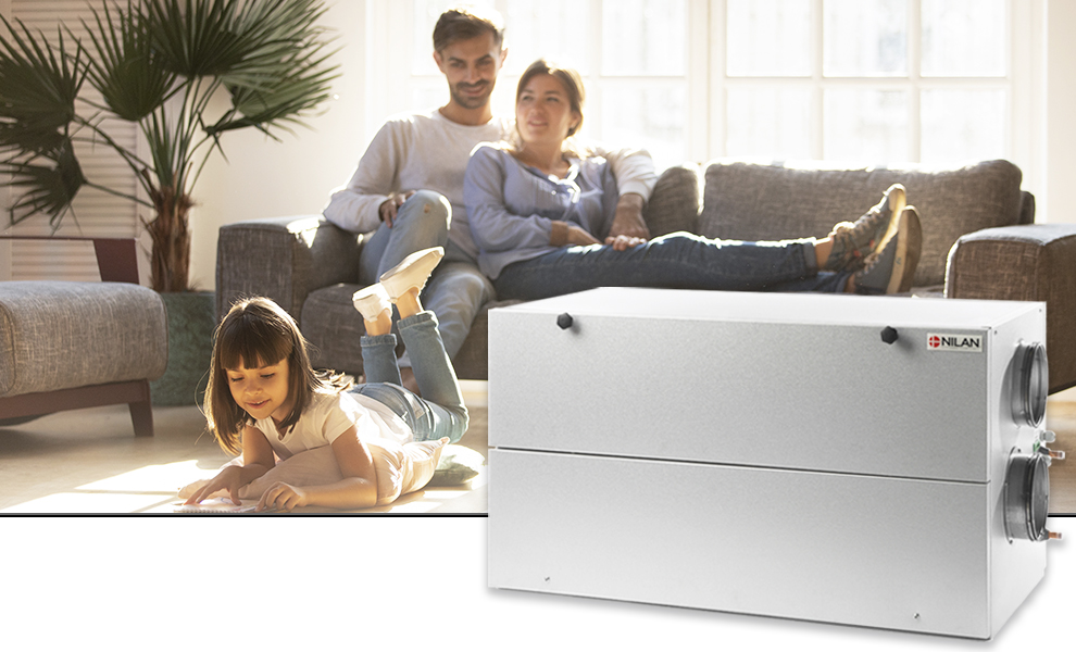
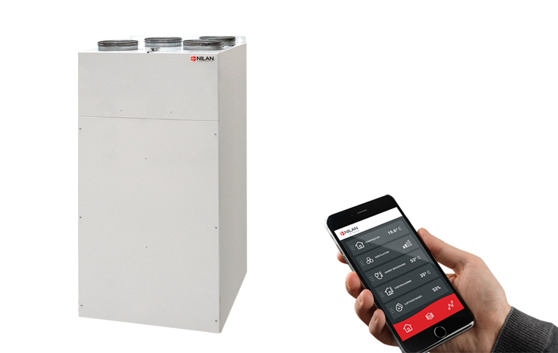
Nilan Comfort 300LR is a ventilation unit that is typically used in single-family dwellings and terraced houses.

The unit is often installed in an unused loft so it does not take up space in the utility room. Placing it in the loft also means that it is easy to block potential noise from the unit so it does not enter the dwelling. 
 
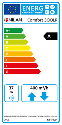
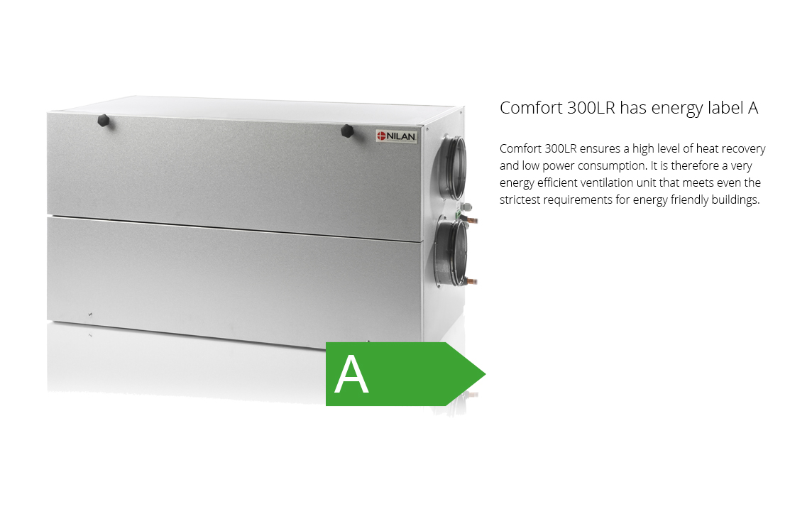
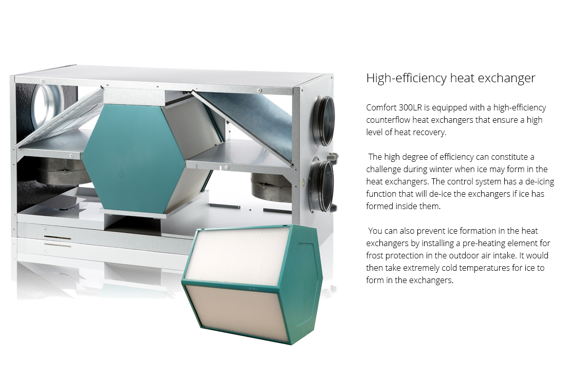
Comfort 300LR creates a good indoor climate in the dwelling. The unit also ensures limited heat loss due to its highly efficient counterflow heat exchanger. It has therefore been given the high energy efficiency rating A. 
 

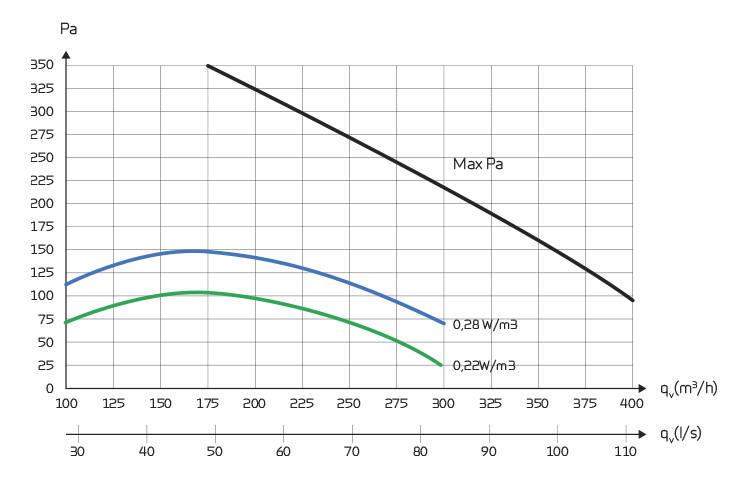
Airflow (see planning data for SEL/SFP values)

Min : 100 m3/h
Max : 400 m3/h

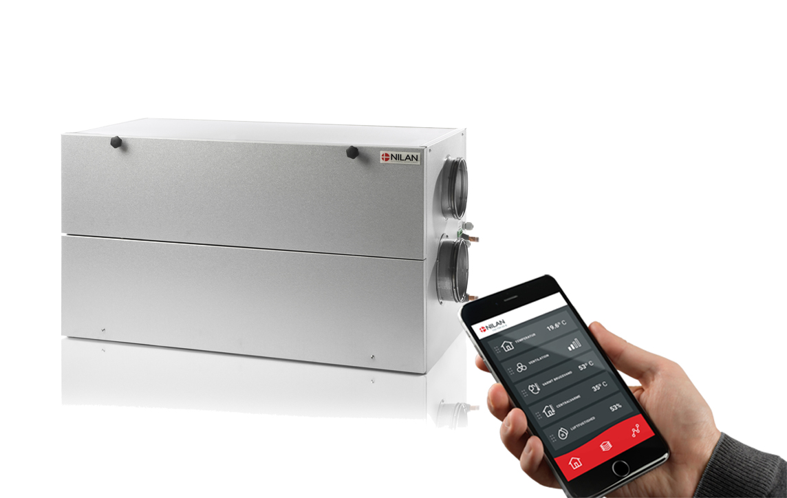
Nilan App - Control the ventilation and heat pump directly from the mobile phone

Nilan has developed an App with great features where the user can control the ventilation and heat pump directly from the mobile phone. The App is intuitive, easy and safe to use, and allows the user to e.g. set the room temperature. More ventilation units can be connected using the same App to control the indoor climate in e.g. both the dwelling and the holiday home. More users can be connected the same App.

When purchasing a Nilan gateway, the user can access the unit via the Nilan App.

Get more information on the Nilan App


Dimensions (W x D x H) 1000 x 508 x 560 mm
Weight 45/33 kg (*1)
Plate type casing Aluzinc steel plate
Heat exchanger type Polyethylenterephthalat counter flow heat exchanger
Fan type EC, constant volume
Filter class Greencycle ISO Coarse 75% (G4)
Duct connections Ø160 mm
Condensate drain PVC Ø20 x 1,5 mm
Supply voltage 230V 50/60 Hz
Max. input/power 270W / 2,2A
Standby power 3W
Tightness class IP31
Ambient temperature -20 / +60 °C
Leakage classification A1 (*2)
Heat loss 0,82 W/m2K (*3)
Heat loss classification T2

*1 33 kg is without side plates and exchanger
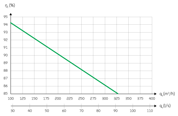
*2 Testet according to EN13141-7
*3 Testet according to EN1886

Capacity

Capacity of standard unit as a function of qv and Pt ext

SEL values according to EN 13141-7 are for standard units with ISO Coarse >75% (G4) filters and without heating element. 

SEL values comprise the unit´s total power comsumption excl. control.  

Attention! The SEL values are measured and stated as a total value for both fans.

Temperature efficiency

Temperature efficiency for units with counterflow heat exchanger according to EN13141-7.
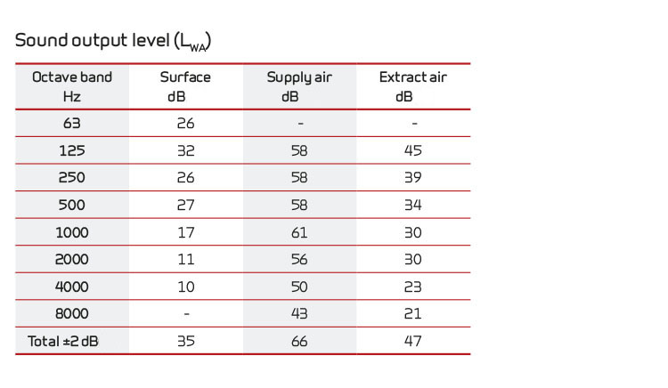
Sound data

Sound data for qv = 200 m3/h and Pt ext = 100 Pa according to EN 9614-2 for surfaces and EN 5136 for ducts.

Sound output level LWA drops with falling air volume and falling back pressure.

Sound output level LpA at a given distance will depend on acoustic conditions in the place of installation.

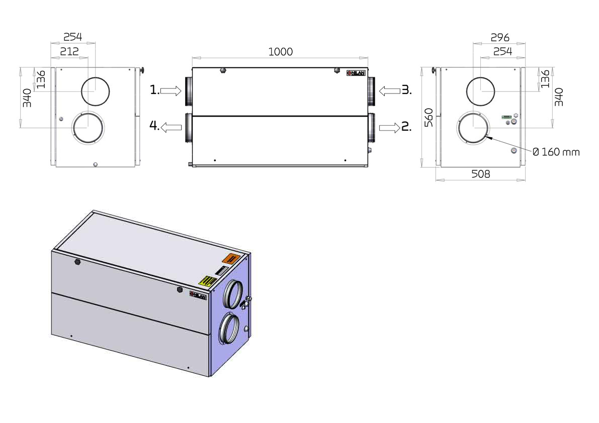
You can download AutoCad or Revit drawings with BIM data on several Nilan ventilation and heat pump solutions - the list is constantly being expanded.
With BIM data, you get all the necessary technical data to draw and calculate Nilan constructions in 3D. Click here to get more about BIM data on Nilan units
 

Dimensional drawing Comfort 300LR (Right version). Comfort 300 LR can function as both a right-facing and a left-facing version by swapping the doors and the back plate.

Connections:
1. Outdoor air
2. Supply air
3. Extract air
4. Discharge air

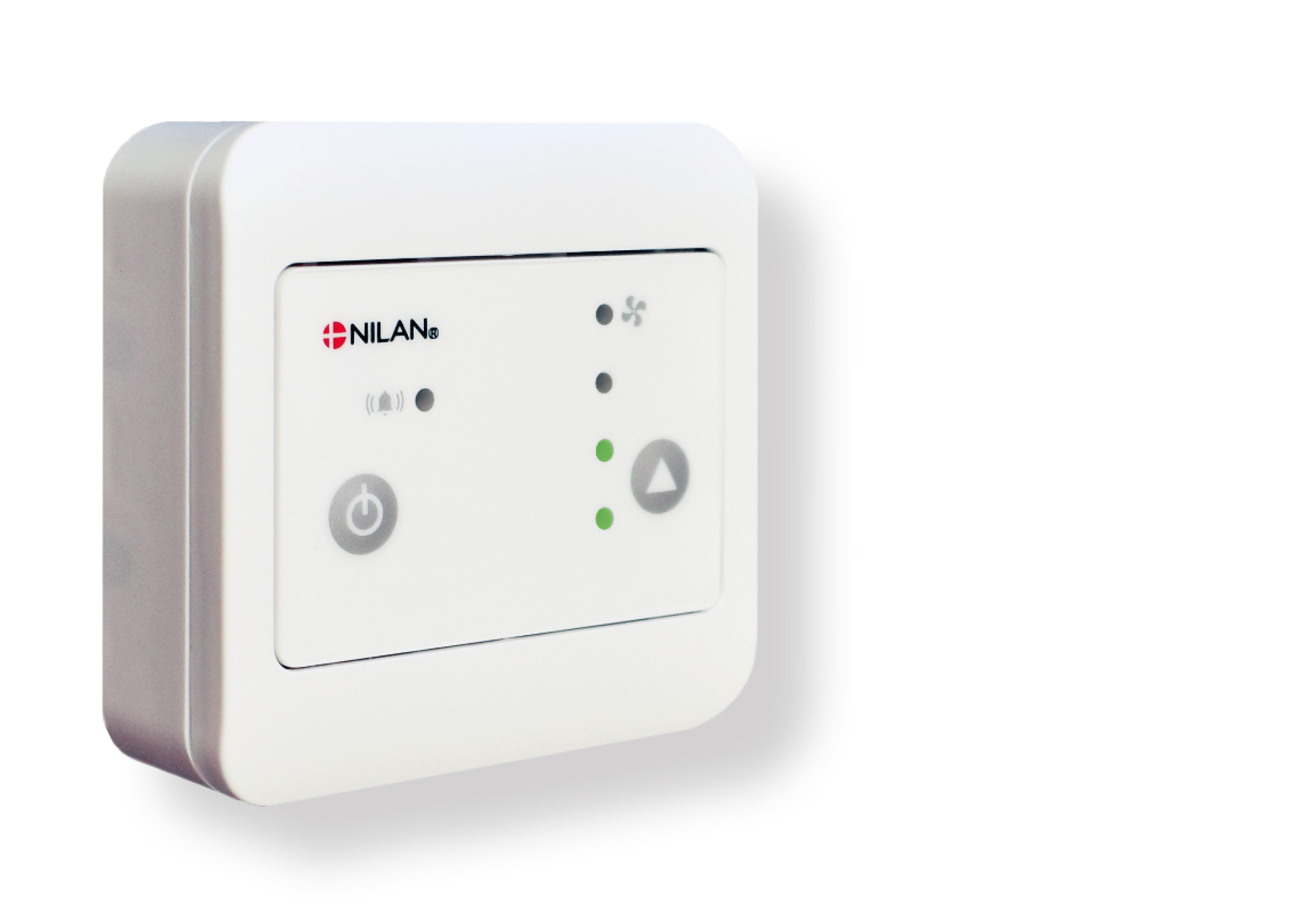
CTS400 is a simple and intuitive control panel with a complex control system that contains many useful functions. On the control panel you can set the fan speed level, turn the unit on and off and see potential alarms.

When installed in rental properties, hotels etc., you can lock the panel so tenants cannot turn off the unit and/or alter the fan speed level.

The many functions of the control system enable you to connect, for instance, after-heating elements and a CO2 or VOC sensor. The control system includes, as standard, user selection programs, an intelligent humidity control system and an integral fire automation system.  

CTS400 has open Modbus communication that enables connection to external CTS systems.

The Modbus connection can also be connected to a Nilan gateway cloud solution that allows you to control and monitor the unit via a smartphone App solution. 

Functions overview   +Standard
- Accessories
Filter monitor Filter alarm with timer (the default setting is 90 days). You can set this to anything between 1 - 360 days. -
Bypass The air will bypass the heat exchanger if heat recovery is not required. +
Humidity control system Enables a higher or lower fan speed level at a high/low level of humidity. +
Summer/winter mode Setting for when the unit is to operate in summer or winter mode respectively. +
Stop at low room temperature Stops ventilation at low room temperature if, for instance, the heat supply fails. +
De-icing Automatic function that de-ices the exchanger based on temperature. +
Temperature control Controls the bypass and potential after-heating elements in accordance with the selected room temperature. +
Air volume Enables stepless setting of four fan speed levels for supply air and extract air. +
CO2- / VOC-styring Enables the addition of an external CO2 or VOC control system. -
Fire automation system Enables the addition of a fire automation system to control 1-2 fire dampers. -
Electrical after-heating element Enables the addition of an electrical after-heating element. -
Water after-heating element Enables the addition of a water after-heating element. -
User selections 1 and 2 User selection is used for external potential free control signals from, for instance, a cooker hood. +
Fire thermostat/ external fire automation system You can connect a fire thermostat or an external fire automation system. +
Locking the control panel You can lock the control panel so it cannot be turned off and/or the fan speed level cannot be altered. +


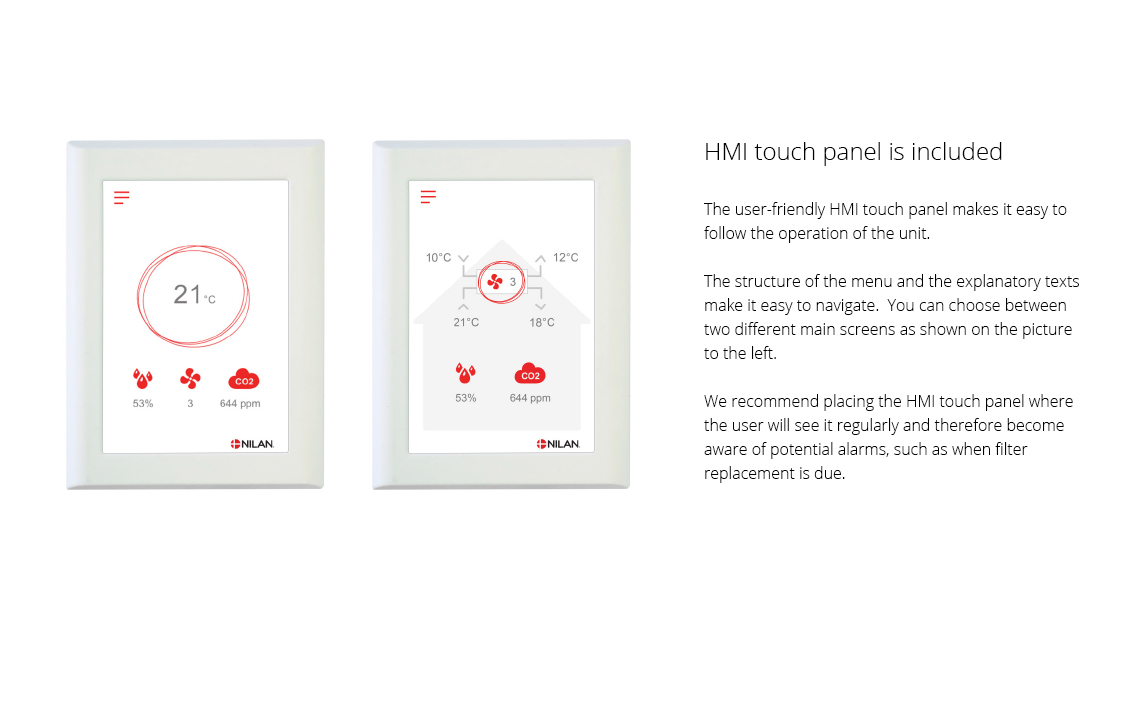
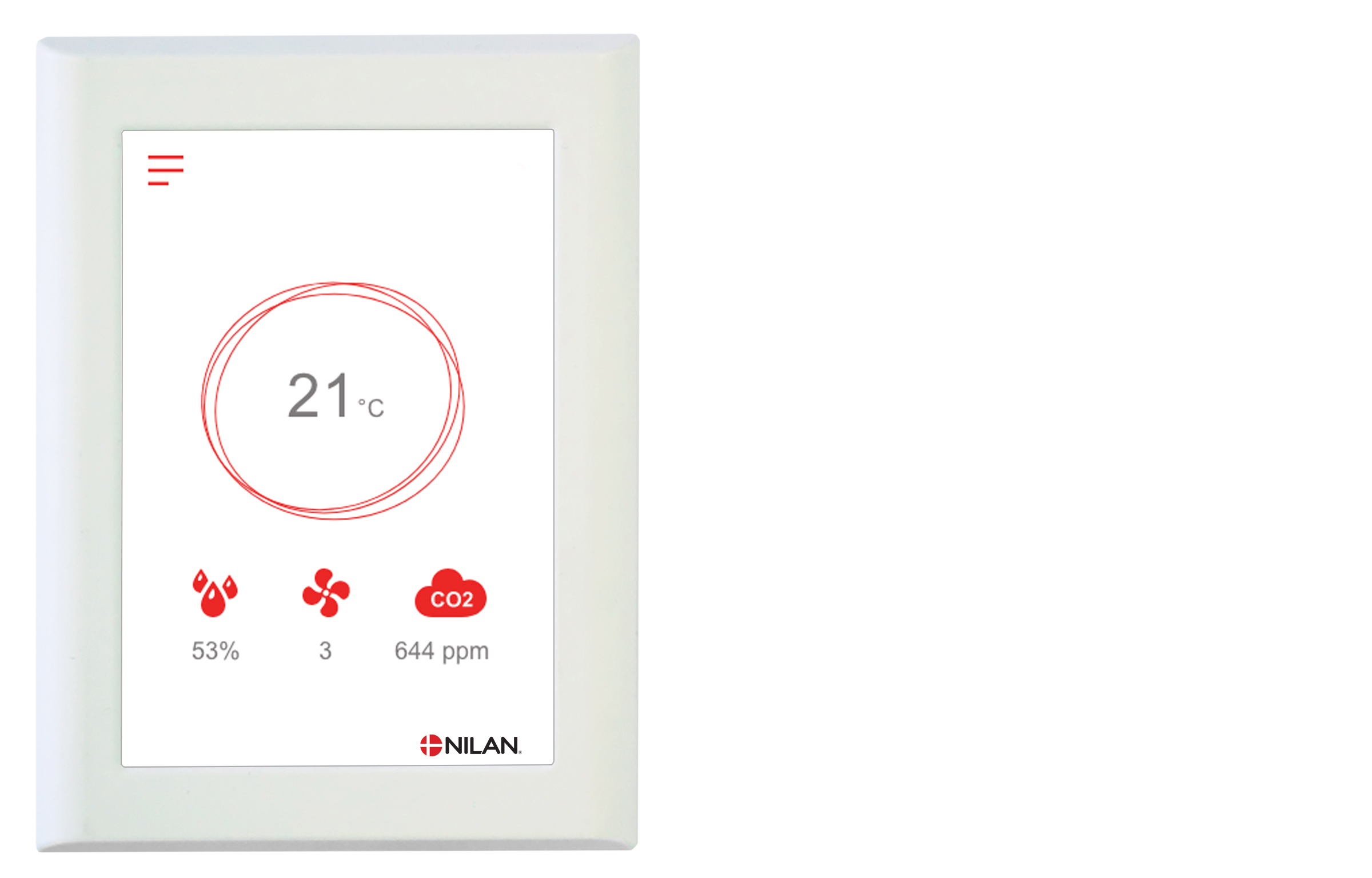
The CTS602 control system is an advanced control system with many settings options. The control system is supplied with factory default settings that can be adapted to the operational requirements in order to achieve best possible operation and utilisation of the unit.

The HMI Touch panel provides an overview of the current operation of the unit, and the structure of its menu makes it easy to navigate for both user and installer.

External communication
The CTS602 control system has an open Modbus RS485 protocol that can be used for communication via external CTS systems.

Functions overview   +Standard
-Accessories
Alarms Description of errors indicated with alarms. Alarm log displaying the latest 16 alarms. +
Joint alarm The CTS602 control system has an output signal that is activated in the case of an alarm. It can be connected to, for example, external automation.  
Filter monitor Filter alarm with timer that can be set to 30/90/180/360 days. +
Data display An overview of the current operation with regards to temperatures, fan speed level etc. +
Week program The CTS602 control system has 3 week programs that can be set individually (the default setting is “off”). +
Humidity control system Enables a higher or lower degree of ventilation at a high/low level of humidity. +
Air quality Enables you to adjust the degree of ventilation depending on the CO2 level in the air. -
Winter low You can prevent a low level of humidity in the dwelling by activating low ventilation at low outdoor temperatures. +
Temperature regulation Enables you to control the operation of the unit in accordance with the room temperature. +
Summer/winter mode You can set the unit to operate in summer or winter mode.  
Language You can choose from more than 10 languages in the control panel. +
User levels The menu in the control panel is divided into 3 user levels: User/Installer/Factory. +
User selection 1 Enables you to override the operating mode via an external potential free signal. +
User selection 2 Enables you to override the operating mode as well as user selection 1 via an external potential free signal. -
Electrical after-heating element An electrical after-heating element allows you to control the supply air temperature. In this way the unit can help heat the dwelling. -
Water after-heating element A water after-heating element allows you to control the supply air temperature. In this way the unit can help heat the dwelling. -
Frost protection In order to protect a potential water after-heating element against frost damage, the unit will stop and display an alarm if the temperature in the water after-heating element becomes too low. -
Air exchange Stepless setting of four fan speed levels. The supply air and the extract air can be set individually. +
De-icing Based on temperature, this automatic function de-ices the counterflow heat exchanger if ice has formed within it. +
Room low Safety function that will cause the ventilation unit to stop if the heating system for the dwelling fails. This will prevent the unit from cooling the dwelling even further.  +
External heating The ventilation unit can control an external heat supply in accordance with the current room temperature. +
External fire automation system You can connect the ventilation unit to an external fire automation system or to a fire thermostat. This will signal to the unit whether to stop or continue operation. +
Integral fire automation system The ventilation unit is available with an integral fire automation system that can control fire and smoke dampers. -
Pressure sustaining regulator You can install a pressure sustaining regulator on the side of both the extract air and the supply air (applies to CTS602 control - not CTS602 light). -
Delayed start-up You can activate a delayed start-up of the fans if you install, for instance, a shut-off damper. +
Restore settings You can save the current settings and subsequently restore them if, for instance, the user has altered the settings on the unit. You can also reinstall the default settings. +
Manual operation Different functions can be tested manually. +
Energy saving function You can activate a power saving function of the operation. +
Modbus  You can set the Modbus address of the unit. The default setting is 30. +
Data logging It is possible to log the operational data of the unit every 1 - 120 min. Alarms are logged when they occur. +
Control panel You can choose from 2 different images for the main screen. +

You can find further information about all the functions in the Software and Installation instructions for the unit.


ATTENTION! When positioning the unit, you should always consider future services and maintenance. It is recommended that you leave a minimum of 60 cm of clear space in front of the unit.

It must be easy to replace filters and it must be possible to replace, for instance, fans and other components.

ATTENTION! The unit must be level to enable proper drainage from the condensate tray.

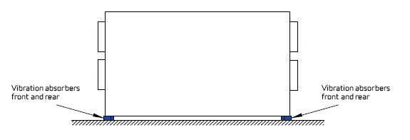
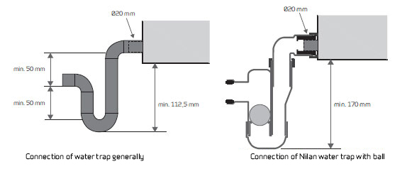
The unit makes little noise and produces only weak vibrations, but you should still take into account potential vibrations that can spread from the unit to individual building components. In order to separate the unit from its foundation, it is therefore recommended that you install vibration absorbers under the unit. There should be approx. 10 mm distance to other building components and to permanent fixtures.

Condensate drain

ATTENTION! You MUST install a water trap in connection with the condensate drain to ensure that condensate water can drain away. If you set up the unit outside the climate screen, it is important to use a heating cable to prevent the condensate drain from icing up. Frost protection of the unit is the installer's responsibility.

Accessories